Steam turbine-part-1-Steam turbine parts-How does a steam turbine work?
Steam Turbine

How does a steam turbine work?
ans: In simple terms, a rotary engine works by using a heat offer (gas, coal, nuclear, solar) to heat water to terribly high temperatures until it's converted into steam. As that steam flows past a turbine's spinning blades, the steam expands and cools.
Steam turbine is one of the most
important prime mover for generating electricity. This falls der the category
of power producing turbo-machines. In the turbine, the energy level of the
working
coes on decreasing along the flow
stream. Single unit of steam turbine can develop power ranging I mW to
1000 mW. In general, 1 mW, 2.5 mW, 5 mW, 10 mW, 30 mW, 120 mW, 210 mW, 250 mW,
350 mW, 500 mW, 660 mW, 1000 mW are in common use. The thermal efficiency of
modern steam power plant above 120 mW is as high as 38% to 40%.
The purpose
of turbine technology is to extract the maximum quantity of energy from the
working fluid, to convert it into useful work with maximum efficiency, by means
of a plant having maximum reliability, minimum cost, minimum supervision and
minimum starting time. This chapter deals with the types and working of various
types of steam turbine.
PRINCIPLE OF
OPERATION OF STEAM TURBINE
The principle
of operation of steam turbine is entirely different from the steam engine. In
reciprocating steam engine, the pressure energy of steam is used to overcome
external resistance and the dynamic action of steam is negligibly small. But
the steam turbine depends completely upon the dynamic action of the steam.
According to Newton's Second Law of Motion, the force is proportional to se
rate of change of momentum (mass x velocity). If the rate of change of momentum
is caused in the
Cam by allowing a high velocity jet of
steam to pass over curved blade, the steam will impart a force to w blade. If
the blade is free, it will move off (rotate) in the direction of force. In
other words, the motive a steam turbine is obtained by the rate of
change in moment of momentum of a high velocity jet am impinging on a curved
blade which is free to rotate. The steam from the boiler is expanded in s or
nozzle where due to fall in pressure of steam, thermal energy of steam is
converted into energy of steam, resulting in the emission of a high velocity
jet of steam which, Principle of - impinges on the moving vanes or blades of
turbine.
ached on a
rotor which is mounted on a shaft supported on bearings, and here steam underage
in direction of motion due to curvature of blades which gives rise to a change
in momentum and therefore a force. This constitutes the driving force of
the turbine. This arrangement is It should be realized that the blade obtains
no motive force from the static pressure of the steam or any impact of the jet,
because the blade in designed such that the steam jet will glide on and off the
hi without any tendency to strike it.
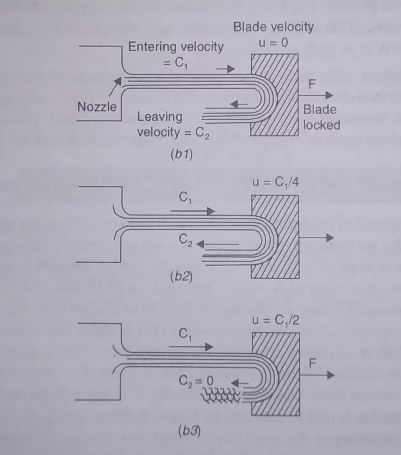
when the blade is
locked the jet enters and leaves with equal velocity thus develops maximum
force if we neglect friction in the blades. Since the blade velocity is zero
mechanical work is done. As the blade is allowed to speed up, the leaving
velocity of jet from the blade reduces, which reduces the force. Due to blade
velocity the work will be done and maximum work done when the blade speed is
just half of the steam speed. In this case, the steam velocity from the blade
is near about zero i.e. it is trail of inert steam since all the kinetic energy
of steam is converted into work The force and work done become zero when the
blade speed is equal to the steam speed. From the above discussion, it follows
that a steam turbine should have a row of nozzles, a row of moving blades fixed
to the rotor, and the casing (cylinder). A row of nozzles and a raw of moving
blades constitute a stage of turbine.
CLASSIFICATION OF STEAM TURBINE
Steam turbine may be classified as
follows:
(A) On the
Basis of Principle of Operation:
(i) Impulse
turbine (a) Simple, (b) Velocity stage, (c) Pressure stage, (d) combination of
(b) and (c)
(ii)
Impulse-reaction turbine (a) 50% (Parson's) reaction, (b) Combination of impulse
and reaction.
Impulse Turbine: If the flow of steam through the nozzles
and moving blades of a turbine takes place in such a manner that the steam is
expanded only in nozzles and pressure at the outlet side the blades is equal to
that at inlet side; such a turbine is termed as impulse turbine because it
works on the principle of impulse. In other words, in impulse turbine, the drop
in pressure of steam takes place only in nozzles and not in moving blades. This
is obtained by making the blade passage of constant cross-section area
As a general
statement it may be stated that energy transformation takes place only in
nozzles and O moving blades (rotor) only cause energy transfer. Since the rotor
blade passages do not cause any nacelles elation of fluid, hence chances of
flow separation are greater which results in lower stage efficiency.
(i) Impulse-Reaction Turbine: In this turbine, the drop in
pressure of steam takes place in fixed (nozzles) as well as moving blades. The
pressure drop suffered by steam while passing through the Moving blades
causes a further generation of kinetic energy within the moving blades, giving
rise to reaction and adds to the propelling force which is applied through the
rotor to the turbine shaft. Since this turbine works on the principle of
impulse and reaction both, so it is called impulse-reaction turbine. This is
achieved by making the blade passage of varying cross-sectional area
(converging type).
In general,
it may be stated that energy transformation occurs in both fixed and moving
blades. The rotor blades cause both energy transfer and transformation. Since
there is an acceleration of flow in moving blade passage hence chances of
separation of flow is less which results in higher stage efficiency.
(B) On the basis of "Direction of
Flow": (i) Axial flow
turbine, (ii) Radial flow turbine, (iii) Tangential flow turbine.
(1) Axial Flow Turbine. In axial flow turbine, the steam flows along
the axis of the shaft. It is the most suitable turbine for large
turbo-generators and that is why it is used in all modem steam power plants.
(i) Radial Flow Turbine. In this turbine, the steam flows in the radial
direction. It incorporates two shafts end to end, each driving a separate
generator. A disc is fixed to each shaft. Rings of 50% reaction radial-flow
bladings are fixed to each disk. The two sets of bladings rotate counter to
each other. In this way, a relative speed of twice the running speed is
achieved and every blade row is made to work. The final stages may be of axial
flow design in order to achieve a larger area of flow. Since this type of
turbine can be warmed and started quickly, so it is very suitable for use at
times of peak load. Though this type of turbine is very successful in the
smaller sizes but formidable design difficulties have hindered the development
of large turbines of this type. In Sweden, however, composite radial/axial Tlow
turbines have been built of outputs upto 275 MW. Sometimes, this type of
turbine is also known as Lungstrom turbine after the name of its inventor B and
F. Liungstrom of Sweden.
(iii) Tangential Flow Turbine. In this type, the steam flows in
the tangential direction. This turbine is very robust but not particularly
efficient machine, sometimes used for driving power station auxiliaries. In
this turbine, nozzle directs steam tangentially into buckets milled in the
periphery of a Single wheel, and on exit the steam turns

through a
reversing chamber, reentering bucket further round the periphery. This process
is repeated several times, the steam flowing a helical path. Several nozzles
with reversing chambers may be used around the wheel periphery.
(C) On the Basis of Means of Heat
Supply: (1) Single pressure turbine, (i) Mixed or dual
pressure turbine (ii) Reheated turbine. (a) Single (b) Double (i) Single Pressure
Turbine : In this type of turbine, there is single source of steam supply
(i) Mixed or Dual Pressure Turbine : This type of turbines, use two sources of
steam, at different pressures. The dual pressure turbine is found in nuclear
power stations where it uses both sources continuously. The mixed pressure
turbine is found in industrial plants (eg, rolling mill. colliery, etc.) where
there are two supplies of steam and use of one supply is more economical than
the other, for example, the economical steam may be the exhaust steam from
engine which can be utilized in the L. P. stages of steam turbine. Dual
pressure system is also used in combined cycle.
(iii) Reheated Turbine : During its passage through the turbine
steam may be taken out to be reheated in a reheated incorporated in the boiler
and returned at higher tempera-true to be expanded in (Fig. 6,6). This is done
to avoid erosion and corrosion problems in the bladings and to improve the
power output and efficiency. The reheating may be single or double or triple.
(D) On the Basis of Means of Heat
Rejection :
(1) Pass-out or extraction turbine,
(in) Regenerative turbine, (iii) Condensing turbine, (iv) Non condensing
turbine, (v) Back pressure or topping turbine.
(i) Pass-out Turbine. In this turbine, (Fig. 6.4), a
considerable proportion of the steam is ex traced from some suitable point in
the turbine where the pressure is sufficient for use in process heating: the
remainder continuing through the turbine. The latter is controlled by separate
valve-gear to meet the
difference
between the pass-out steam and electrical load requirements. This type of
turbine 15 there is
dual demand of steam-one for power and the other for industrial heating, for
exam car industries. Double pass-out turbines are sometimes used.
G)
Regenerative Turbine. This
turbine incorporates a number of extraction branches, through ob small
proportions of the steam are continuously extracted for the purpose of heating
the bon Goed water in a feed heater in order to increase the thermal efficiency
of the plant. Now a days, all steam power plants are equipped with reheating
and regenerative arrangement.
(iii) Condensing Turbine. In this turbine, the exhaust steam is
condensed in a condenser and the condensate is used as feed water in the boiler.
By this way the condensing turbine allows the steam to expand to the lowest
possible pressure before being condensed. All steam power plants use this type
of turbine.
(iv) Non-Condensing Turbine. When the exhaust steam coming out from the
turbine is not condensed but exhausted in the atmosphere is called
non-condensing turbine. The exhaust steam is not recovered for feed water in
the boiler.
(v) Back Pressure or Topping Turbine. This type of turbine rejects the
steam after expansion to the lowest suitable possible pressure at which it is
used for heating purpose. Thus back pressure turbine supplies power as well as
heat energy.
The back pressure turbine generally
used in sugar industries provides low pressure steam for heating apparatus,
where as a topping turbine exhausts into a turbine designed for lower steam
conditions.
(E) On the Basis of Number of Cylinder:
Turbine may be classified as (i) Single cylinder and (ii) Multi-cylinder.
(i) Single Cylinder. When all stages of turbine are housed in one
casing, then it is called single cylinder. Such a single cylinder turbine uses
one shaft.
(ii) Multi-Cylinder. In large output turbine, the
number of the stages needed becomes so high that additional bearings are
required to support the shaft. Under this circumstances, multi-cylinders are
used.
(F) On the Basis of Arrangement of
Cylinder Based on General Flow of Steam. (i) Single flow, (ü) Double flow, and
(iii) Reversed flow
Single Flow. In a single flow turbines,
the steam enters at one end, flows once [Fig. 6.5(a)] through
The ladings in a direction approximately parallel to this axis, emerges at the other end. High pressure cylinder uses single flow. This is also common in small turbines.I uses
single flow. This is also common in small turbines.

Double Flow. In this type of turbines, the steam enters at
the center and divides, the two portions passing axially away from other
through separate sets of balding on the same rotor Fig. 6.5(b). The low
Pressure
cylinder normally uses double flow). This type of unit is completely balanced
against thrust and gives large area of flow through two sets of beading. This
also helps in reducing the height as mass flow rate becomes half as compared to
single flow for the same conditions,
Reversed Flow. Reversed flow arrangement is
sometimes used in h.p, cylinder where : temperature steam is used on the larger
sets in order to minimize differential expansion i.e. expansion of rotor and
casing. The use of single, double and reversed flow .
(G) On the Basis of Number of Shaft ()
Tandem compound, (ii) Cross compound
(1) Tandem Compound. Most multi-cylinder turbines drive a
single shaft and single generate Such turbines are termed as tandem compound
turbines.
(ii) Cross Compound. In this type, two shafts are used
driving separate generator. The may be one of turbine house arrangement,
limited generator size, or a desire to run shafting at half speed. The latter
choice is sometimes preferred so that for the same centrifugal stress, longer
blades may be used giving a larger leaving area, a smaller velocity and hence a
small leaving loss.
(H) On the Basis of Rotational Speed
(i) constant speed turbines (ii) Variable speed turbines
(1) Constant Speed Turbines. Requirements of rotational speed are
extremely rigid in turbines which are directly connected to electric generators
as these must be a-c unit except in the smallest sizes and must therefore run
at speeds corresponding to the standard number of cycles per second and
governed by the following equation :
N= 120 x Number of cycles per second = 120 f/p
Number of poles
The minimum number of poles, in a
generator is two and correspondingly the maximum possible speed for 60 cycle is
3,600 rpm; for 50 c/s of frequency, the speeds would be 3,000, 1500 and 750 rpm
for 2.4 and 8 poles machines respectively.
(in) Variable Speed Turbines. These turbines have geared units and may have
practically any speed ratio between the turbine and the driven machine so that
the turbine may be designed for its own most efficient speed. Such turbines are
used to drive ships, compressors, blowers and variable frequency generators,
THE SIMPLE IMPULSE TURBINE
This type of
turbine works on the principle of impulse and is shown diagrammatically. It
mainly consists of a nozzle or a set of nozzles, a rotor mounted on a shaft,
one set of moving blades attached to the rotor and a casing. The uppermost
portion of the diagram shows a longitudinal section through the upper half of
the turbine, the middle portion shows the development of the nozzles and balding
i.e. the actual shape of the nozzle and balding, and the bottom portion shows
the variation of absolute velocity and absolute pressure during flow of steam
through passage of nozzles and blades. The example of this type of turbine is
the de-Laval Turbine,
It is obvious from the figure that the
complete expansion of steam from the steam chest pressure to the exhaust
pressure or condenser pressure takes place only in one set of nozzles i.e. the
pressure drop takes place only in nozzles. It is assumed that the pressure in
the recess between nozzles and blades
remains the
same . The steam at condenser pressure or exhaust pressure enters the bald and comes out same pressure i.e. the pressure of steam in the blade passages
remains approximately cons Juan to the condenser pressure. Generally,
converging-diverging nozzles are used. Due to the relatively
ratio of
expansion of steam in the nozzles, the steam leaves the nozzles at a very high per
sonic), of about 1100 m/s. It is assumed that the velocity remains constant in
the recess between
sees and the blades. The steam at such
a high velocity enters the blades and reduces along the Ce of blades and comes
out with an appreciable amount of velocity (Fig. 6.6).
As it has been already shown, that for
the good economy or maximum work, the blade seeded should be one half of the
steam speed so blade velocity is of about 500 m/s which is very en high. This
results in a very high rotational speed, reaching 30,000 r.p.m. Such high
rotational speeds can only be utilized to drive generators or machines with
large reduction gearing arrangements.
In this
turbine, the leaving velocity of steam is also quite appreciable resulting in
an energy loss, called "carry over loss" or "leaving velocity
loss”. This leaving loss is so high that it may amount to about 11 percent of
the initial kinetic energy. This type of turbine is generally employed where
relatively small power is needed and where the rotor diameter is kept fairly
small.

COMPOUNDING OF IMPULSE TURBINE
Compounding
is a method for reducing the rotational speed of the impulse turbine to
practical limits. As we have seen, if the high velocity of steam is allowed to
flow through one row of moving blades, it produces a rotor speed of about 30,000
r.p.m. which is too high for practical use. Not only this,
the leaving
loss is also very high. It is therefore essential to incorporate some
improvements simple impulse turbine for practical use and also to achieve high
performance. This is possible by ing use of more than one set of nozzles,
blades, rotors, in a series, keyed to a common shaft, so the the steam pressure
or the jet velocity is absorbed by the turbine in stages. The leaving loss also
will be less. This process is called compounding of steam turbines. There are
three main types
(a) Pressure-compounded impulse
turbine.
(b)
Velocity-compounded impulse turbine.
(c) Pressure
and velocity compounded impulse turbine.
PRESSURE
COMPOUNDED IMPULSE TURBINE
In this type
of turbine, the compounding is done for pressure of steam only i e. to reduce
the high rotational speed of turbine the whole expansion of steam is arranged
in a number of steps by employing a number of simple turbine in a series keyed
on the same shaft as shown. Each of these simple impulse turbine consisting of
one set of nozzles and one row of moving blades is
set of nozzles and one row of moving
blades is known as a stage of the turbine and thus this turbine consists of
several stages. The exhaust from each row of moving blades enters the
succeeding set of nozzles. Thus we can say that this arrangement is nothing but
splitting up the whole pressure drop (Fig. 6.7).

from the
steam chest pressure to the condenser pressure into a series of smaller
pressure drop across several stages of impulse turbine and hence this turbine
is culled, pressure-compound impulse turbine.
The pressure and velocity variation are
also shown. The nozzles are fitted into a diaphragm which is locked in the
casing. This diaphragm separates one wheel chamber from another. All rotors are
mounated on
the same shaft and the blades are attached on the rotor. The rotor (i.e. disc)
may be keyed shaft or it may be integral part of shaft. The expansion of steam
only takes place in the nozzles while pressure remains constant m
ins constant in the
e ING blades because each stage is a
simple impulse turbine. So it is obvious from the pressure curve
race between any two consecutive
diaphragms is filled with steam at constant pressure and - either side of the
diaphragm is different. Since the diaphragm is a stationary part, there is
trance between the rotating shaft and the diaphragm. The steam tends to leak
through this cecal for which devices like labyrinth packing, etc. are used.
Since the drop in pressure of steam per
stage is reduced, so the steam velocity leaving the nozzles Monte-ring the
moving blades is reduced which reduces the blade velocity. Hence for good
economy of
um work shaft speed is significantly
reduced so as be reduced by increasing the number of stages
ding to ones need. The leaving velocity
of the last stage of the turbine is much less compared to the DE Laval turbine
and the leaving loss amounts to about 1 to 2 percent of the initial total
available energy. This turbine was invented by the late prof L. Gateau and so
it is also known as Gateau Turbine.


I would suggest must go for best electrician. we provide Electrical Repair Springfield Mo at affordable prices. for more info visit our website.
ReplyDelete